Whiteboard Intelligent and Programmable Erasing Robot
Automated, vision based path planning and feedback controls robot with detachable erasing mechanism.
April 29th 2024
Nathan Sun
Zizai Ma
Peng Qiu
Yiming Yu
Zhonghao Wei
Click below to view the full project report:
Project Snapshot


Goal:
Design an autonomous whiteboard cleaning robot that magnetically attaches to vertical boards and performs selective area cleaning.
My Role:
Mechanical design, magnetic force analysis, control implementation (PID), testing & validation, camera localization integration, path planning and coverage path planning.
Key Achievements:
-
Successfully climbed and operated on vertical whiteboards without slipping
-
Implemented closed-loop motor control using IMU feedback
-
Designed magnetic adhesion system based on quantified force modeling
-
Integrated RealSense D435 + AprilTags for visual localization
Technologies Used:
Arduino, PID Control, Neodymium Magnets, IMU (MPU-6050), Intel RealSense D435, AprilTags, DC motors with encoders, LiPo battery system
Stage 1: Initial Prototype and Testing Validation (WIPER V1)
Problem Framing & Customer Dicsovery
The project began with structured problem definition through professor interviews and stakeholder feedback, as well as site visit and surveying at Boston University classrooms equipped with whiteboards.


We formalized the problem statement and collected structured customer requirements (Project Concept Review)
This phase grounded the project in measurable user-driven constraints rather than assumptions.
Customer Priority Matrix
After gathering customer inputs, we translated qualitative demands into a quantitative priority matrix

Top ranked requirements:
1) Must clean dry erase markers
2) Safety protection for humans
3) Must last multiple board cleaning sessions
4) Replaceable & re-cleanable eraser
5) Replaceable power supply
6)Clean by selected sections
7)Localize and plan path
Engineering Specifications
Customer priorities were converted into measurable engineering constraints

This formally defined WIPER V1 as a validation platform.
We also performed Pugh analysis against existing products to justify our design direction over benchmarked solutions.

Eraser Performance Testing (Material Selection)
Before building a magnetic climbing robot, we validated the core cleaning mechanism experimentally.
We conducted controlled testing on:
-
Applied normal force vs cleanliness
-
Wiping velocity vs cleanliness
-
3M vs EXPO erasers
Key Findings:
From Trial 1 (constant velocity, varying load):
-
EXPO required ~1500 g to achieve level 5 cleanliness
-
3M achieved level 5 cleanliness at ~700–1000 g
From Trial 2 (constant load, varying velocity):
-
Increased velocity slightly reduced EXPO performance
-
3M showed stable cleaning effectiveness across speeds
Conclusion (based on measured data):
-
3M melamine achieved level-5 cleanliness at ~700–1000 g
-
EXPO required ~1500 g
-
Velocity had minimal impact on performance
Friction & Magnetic Suction Validation

Friction testing determined:
μ≈0.21
Magnetic suction calculations were performed to determine minimum adhesion force.
Total suction requirement for stable vertical support was calculated to be approximately 5.6 N.
Using:
F_friction=μ⋅F_magnetic
The selected 15-magnet configuration was analytically validated to support the system mass.
This stage marked the first complete physics-backed verification of vertical feasibility.
Power Component Analysis
Power consumption was analyzed under multiple operating conditions.
With:
-
11.1 V battery
-
33.3 Wh capacity
-
3000 mAh rating
Estimated duty-cycle scenarios confirmed sufficient energy margin for classroom operation.
Both mass-based and electrical load approaches were evaluated to ensure runtime feasibility.


Weight Budget Analysis

A full component-level mass breakdown was completed.
Total estimated system mass:
-
974.5 g nominal
-
1218.13 g with 1.25 safety factor
Major contributors included:
-
Battery: 200 g
-
Motors: 160 g
-
Wheels: 100 g
-
Magnets: 112.5 g
-
Acrylic structure: 290 g
This confirmed that magnetic adhesion calculations must support ~1.2 kg operating mass.
Generation 1 Design Iteration


The Week 8 design description formalized the Generation 1 architecture.
Generation 1 was defined as an engineering validation platform verifying:
-
Magnetic attachment viability
-
Wheel-driven cleaning effectiveness
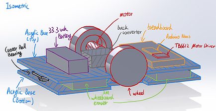
Mechanical Architecture
-
Two-wheel differential drive
-
4 melamine erasers mounted beneath the top plate
-
15 Neodymium magnets (4cm × 1.34cm × 0.5cm)
-
Dual 3mm acrylic base plates
-
1.5 mm magnet standoff from board surface
-
Two caster ball bearings for stability regulation
The bottom acrylic plate carried all magnets and was designed for easy reconfiguration.
The modular structure enabled rapid iteration and magnet configuration changes.


Generation 1 — Prototype Build & Validation
Following requirement definition and experimental validation, the Generation 1 prototype was constructed.
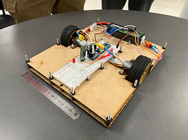


The final V1 assembly integrated:
-
2 DC motors (differential drive)
-
6 Neodymium permanent magnets
-
4 melamine erasers
-
Arduino Nano + motor driver
-
HC-06 Bluetooth module for manual control
-
11.1 V LiPo battery
-
Dual-layer laser-cut 3 mm baseplates
The completed mechanical layout measured approximately 230 mm × 270 mm, with a total system mass aligned with earlier weight budget calculations.

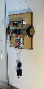
V1 Capabilities
By the end of the build phase, Generation 1 successfully demonstrated:
-
Stable vertical magnetic adhesion
-
Manual mobility across vertical whiteboard surfaces
-
Force-dependent cleaning effectiveness
-
Feasible power budget within battery constraints
V1 functioned as a validated mechanical and electrical platform.
Limitations Identified
-
Manual (Bluetooth) control only
-
No closed-loop heading stabilization
-
No localization or path planning
-
No selective eraser lifting mechanism
These constraints defined the transition requirements for Generation 2.
Generation 1 concluded as a physics-validated prototype confirming the feasibility of magnetic vertical adhesion and force-based cleaning, establishing a stable foundation for autonomous development in subsequent iterations.
Stage 2 — Robot Redesign & Automation Software (WIPER V2)
Stage 2 focused on addressing the mechanical and control limitations identified in Generation 1. The objective shifted from basic feasibility to structural robustness, controllability, and autonomous functionality based on CV, path planning and coverage path planning.


Motor Performance & Slip Testing
To improve WIPER Gen 1.'s stability, systematic testing with strong torqued motors installed was conducted to quantify vertical performance and load capacity.
This motor and rubber wheel formula tested on Gen. 1 is proven to be translatable to the Gen. 2 design
Key findings:
-
No slipping under static loads below ~3290 g
-
No slipping with powered motors
-
Critical drag load (unpowered motors): 1851.4 g

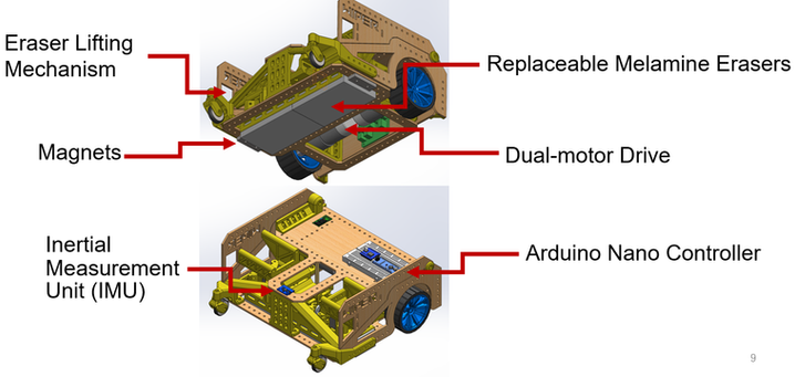
V2 Architecture Concept & Fabrication
With structural and control lessons incorporated, a full redesign (WIPER V2) was proposed.
Core architectural changes
-
Dual-layer structure
Electronics on top, mechanical system below -
Compact centralized body
Improved center of mass distribution -
Single-side liftable eraser mechanism
Sliding bar linkage with rotational actuation -
Floating magnet configuration
Multi-caster support to prevent board contact
Fabrication stages included:
-
Chassis assembly
-
Powertrain installation
-
Raiser mechanism assembly
-
PID tuning


Testing of V2:

PID Controller
To enable precise turning and trajectory correction, a PID-based control framework was implemented using:
-
MPU-6050 IMU (gyroscope + accelerometer)
-
Dual DC motors with encoders
-
Arduino-based low-level control loop
The control system performed:
-
Real-time angle estimation from IMU data
-
Target angle calculation relative to destination
-
Differential motor speed adjustment via adjustMotors()
-
Closed-loop correction until angular error converged
The controller continuously compared current heading to target heading and adjusted motor outputs accordingly.
Result:
-
Stable turning behavior
-
Reduced heading overshoot
-
Repeatable angular positioning
-
Improved straight-line tracking during vertical climbing
Computer Vision with Intel D435 & April Tags
To enable global positioning on the whiteboard, WIPER integrated:
-
Intel RealSense D435 depth camera
-
AprilTag fiducial markers (tagStandard41h12)
-
Python pipeline using:
-
pyrealsense2
-
pupil_apriltags
-
OpenCV
-
AprilTags were mounted at:
-
Four whiteboard corners
-
On WIPER body (robot reference tag)
-
A reference tag defining world coordinate origin
The system computed:
-
Relative X–Y positions
-
Tag yaw orientation
-
Robot pose relative to board coordinate frame
Key Outcomes:
-
Low position error relative to hand measurements
-
Stable tag detection at 2–5 m distance
-
Reliable pose estimation under classroom lighting
-
Partitioned the board into four quadrants


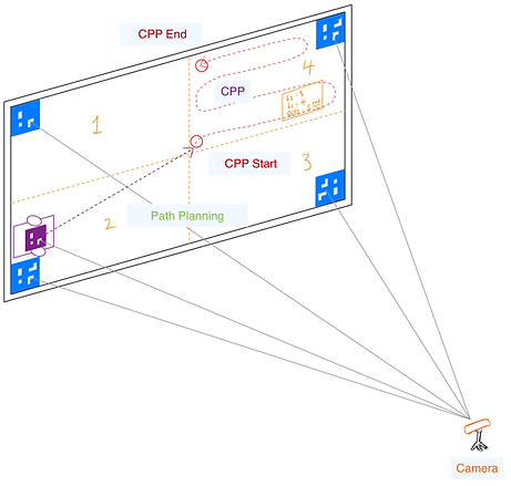
Path Planning & Coverage Path Planning
Once localization and region definition were established, WIPER implemented deterministic path planning.
The planner:
-
Computed start pose
-
Generated waypoint list inside selected region
-
Executed turn-then-translate motion sequence
-
Continuously corrected heading via PID control
Path planning ensured:
-
Directed motion toward region center
-
Efficient traversal without random bouncing
-
Reduced redundant coverage
After reaching a target quadrant, WIPER executed a structured Coverage Path Planning (CPP) algorithm.
The CPP module:
-
Generated parallel sweep lines across region
-
Maintained constant vertical velocity
-
Alternated direction (boustrophedon pattern)
-
Activated eraser during coverage phase only
This ensured:
-
Complete area coverage
-
No missed strips
-
Minimal overlap
The eraser lifting mechanism was coordinated with path execution to prevent unintended cleaning during transit.

Final Implementation and Product Presentation
The final WIPER system integrated mechanical design, embedded control, computer vision, mapping, path planning, and a user interaction interface into a fully autonomous whiteboard cleaning robot.
System Architecture Overview
The completed system was structured into three coordinated layers:
1. Mechanical & Hardware Layer
-
Differential drive system with high-torque DC motors
-
Permanent magnet adhesion array
-
Servo-driven eraser raising mechanism
-
MPU-6050 IMU
-
Intel RealSense D435 depth camera
-
11.1V LiPo battery (33.3 Wh)
-
Dual-layer chassis separating electronics and mechanical components
The mechanical layout ensured stable vertical adhesion, balanced center of mass, and sufficient clearance to prevent magnet–board contact.
User Interface & System Integration
The final system combined:
-
Arduino-based PID motor control
-
Bluetooth communication (HC-06)
-
Python-based vision and planning modules
Software Report
The user interface allowed:
-
Camera initialization and map visualization
-
Quadrant selection via keyboard input
-
Execution of autonomous cleaning sequence
-
Return-to-center or shutdown command
All modules were executed through a small set of Python scripts coordinating high-level planning with embedded motor control.


The completed system demonstrated:
-
Stable magnetic vertical adhesion
-
Closed-loop heading control
-
Vision-based localization
-
Selective quadrant cleaning
-
Structured coverage execution
WIPER evolved into a fully autonomous, vision-guided whiteboard cleaning robot integrating mechanical design, embedded control, and computer vision into a unified robotic platform.
